Skip to main content
Information for:
Teachers
Students
Researchers
Search
Search
User account menu
Log in
QuarkNet
Main navigation
About
About QuarkNet
Centers
Contacts
Join Us
Stories
Data Activities Portfolio
Masterclasses
About Masterclasses
Fermilab/QuarkNet Masterclasses
World Wide Data Day
e-Labs
About e-Labs
Cosmic Ray
CMS
Toggle navigation
Information for:
Teachers
Students
Researchers
Main Navigation:
About
About QuarkNet
Centers
Contacts
Join Us
Stories
Data Activities Portfolio
Masterclasses
About Masterclasses
Fermilab/QuarkNet Masterclasses
World Wide Data Day
e-Labs
About e-Labs
Cosmic Ray
CMS
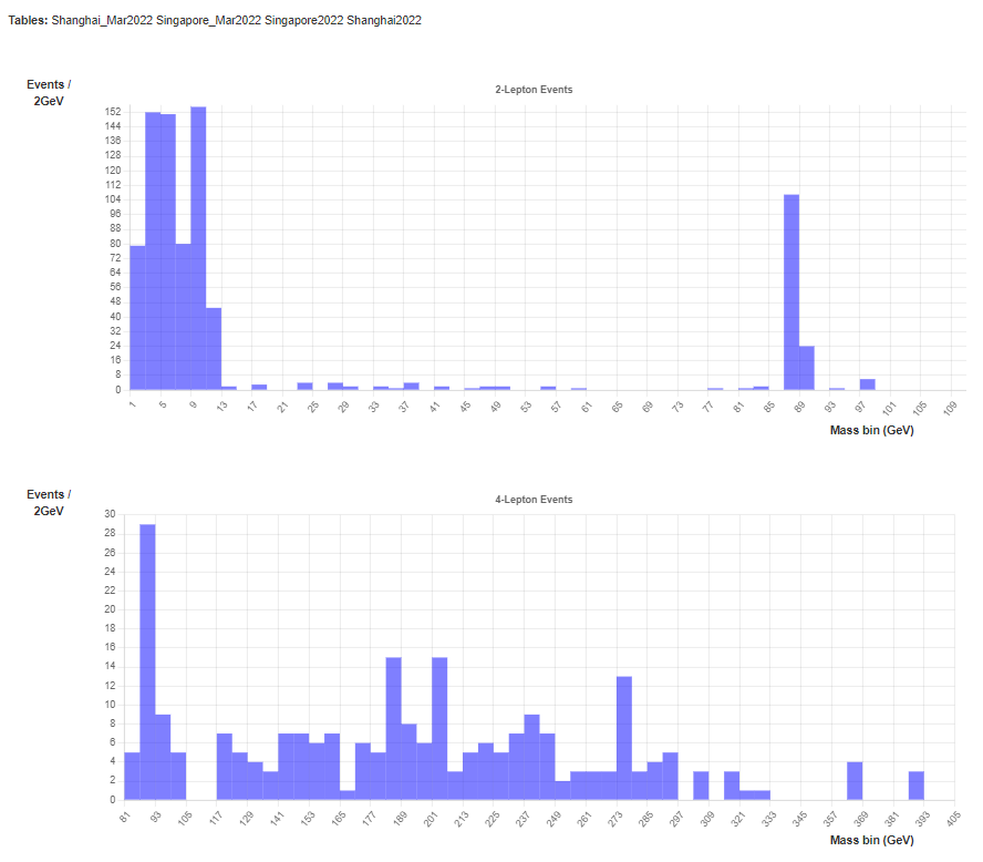
Shanghai and Singapore CMS Masterclass Results 2022
Submitted by
kcecire
Published:
Fri, 03/25/2022 - 09:56
|
Group(s):
LHC Masterclass Library 2022
Mass Plots
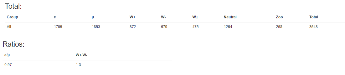
Key Ratios
Published Mass plots