
U of I Quarknet 2014: Scintillation Deposition
John Guhin (Bettendorf High School), Lindsay Matthews (Bettendorf High School), Nathaniel Perk (Bettendorf High School), Peter Bruecken (Bettendorf High School), Moira Truesdell (Bettendorf High School), Yasar Onel (University of Iowa)
Purpose:
The calorimeters at The Compact Muon Solenoid (CMS) at the Large Hadron Calorimeter (LHC) at CERN have had a large exposure to radiation with considerable damage to them. They need to be replaced by more robust radiation hard materials that still maintain a high sensitivity to particle detection. We are testing materials that could replace the current materials that would be more robust to radiation damage while maintaining sensitivity to particle presence.
To this end, we are depositing organic scintillating materials on Quartz plates in an attempt to create materials that are radiation hard yet maintain sensitivity to passage of particles.
Method:
Quartz plates have been shown to be one of the few radiation hard transparent materials, especially to Ultraviolet radiation (UV). When high-energy particles pass through Quartz, they can create Cherenkov radiation in the violet-color range. This radiation is very weak compared to some organic substances that fluoresce light. To combine the sensitivity of the organic substances along with the transparency and radiation hardness of quartz, we will attempt to coat the quartz plates with the organic materials to attain the best of both.
Vacuum deposition was used to coat the quartz plates with the organic scintillation chemicals. Vacuum deposition was chosen because it would adhere the substances to the surface of the Quartz plates somewhat evenly. The plates were then annealed in the absence of oxygen to make the depositions more transparent. Once the organic scintillation material was fixed between two plates, wave-shifting fibers were optically coupled to the quartz plates to pick up the light created by the scintillation. The light from these fibers would then be measured by a photodetector and translated into data to be compared.
Four materials were slated to be tested this way: Naphthalene, Stilbene, Anthracene and P-terphenyl (PTP). All of these substances are known to scintillate with UV radiation. PTP has been used for this before so it was a standard to compare the others against. Each was tested for workability, sensitivity and compatibility with the Quartz plates.
Procedure:
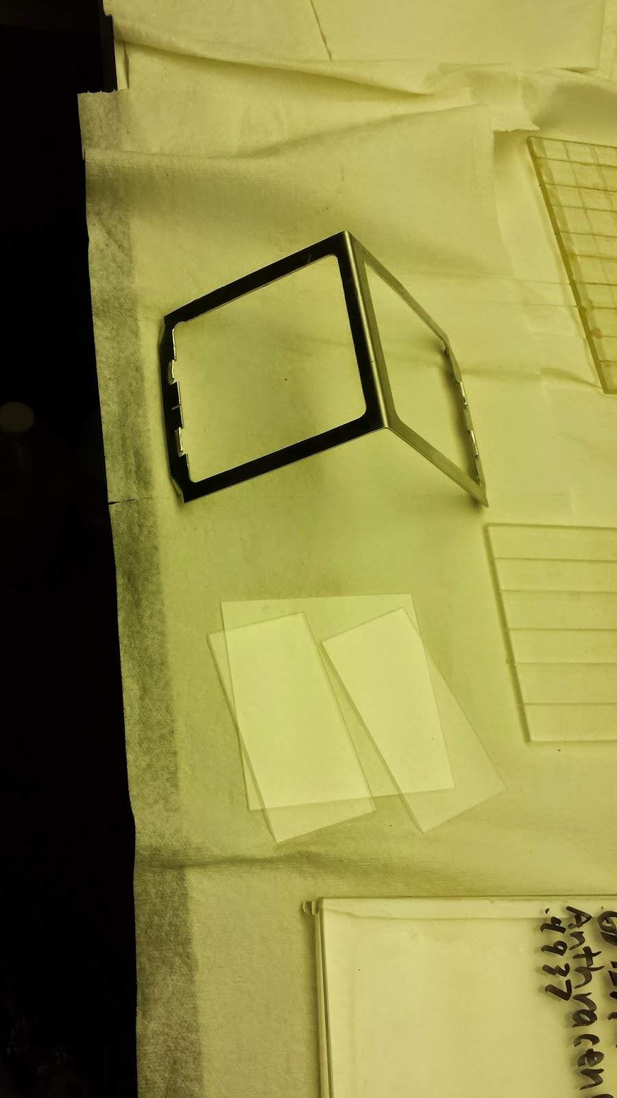
The materials used in the vacuum chamber were one 10 cm x 10 cm x 0.1 cm and two 5 cm x 10 cm x 0.1 cm plates along with an Aluminum “roof” to hold them above a glass cylinder with a Tantalum “boat”. The boat was suspended below the plates by two electrodes. A high current could pass through the boat in order to heat it up.

Prior to evaporating the chemicals, the vacuum must be pumped down to at least 10-6 torr. In order to achieve this very low pressure, everything was cleaned (with acetone while wearing gloves) of all fingerprints and dust to prevent outgassing. All components in the setup were also made of materials that did not outgas. After everything was cleaned, the vacuum pump was pumped down to at least 10-6 torr before heating up the boat to begin plating.
The materials were heated up by a current passing through the Tantalum boat. The contents were heated up slowly, using a rheostat to adjust the current, to the melting temperature. Using the Aluminum stand to hold up the panes, the panes were then coated by the evaporating chemical. The Aluminum roof and the glass cylinder were used to prevent the bell jar from being deposited with the chemical.
After plating was complete, the plates had a cloudy look. The material needed to be crystallized in order to readily pass light through them. The plates were removed and taped together with Kapton® high-temp tape, making sure to have the scintillation chemicals in between them and a gap between the half-plates that is large enough to fit an optical fiber. The tape was also put over the gap to prevent the chemicals from evaporating from the plates.
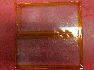
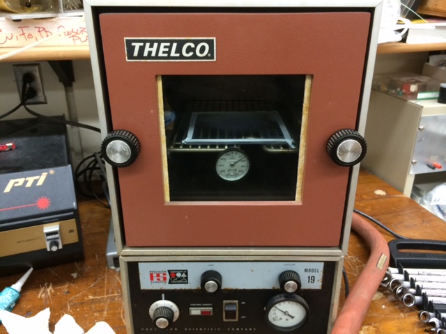
The plates were then placed in a chamber of an air-tight oven. The chamber was evacuated, then filled with nitrogen to prevent oxidation. The chamber was slowly heated up to the chemical’s melting point and slowly cooled to anneal the chemical to a crystalline form. The plate was removed after the annealing process was done, the groove was greased with optical grease, a blue optical fiber was inserted into the greased groove, and the groove was re-greased with the optical fiber inside. The tape was placed over the top of the greased groove.
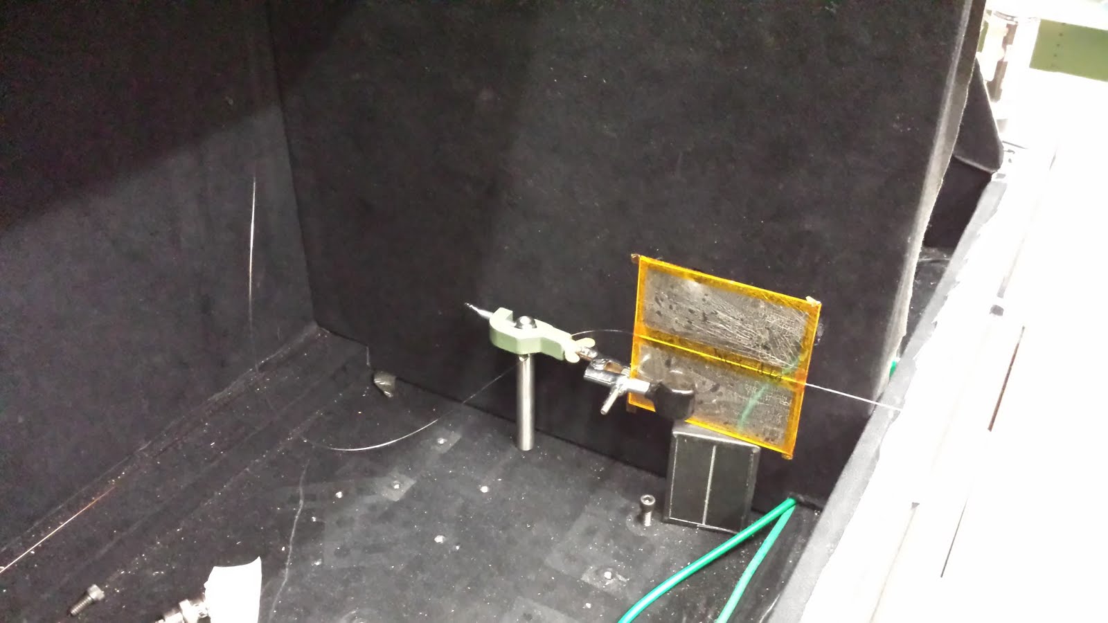
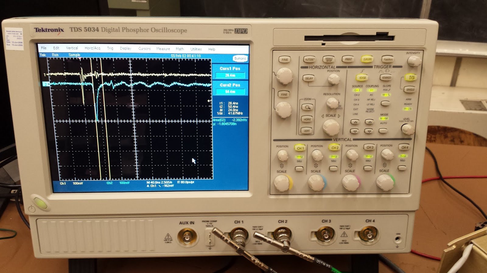
A test was done on the plates to see if they would create light. The plates were put in a dark box and exposed to a 337 nm UV pulsed LASER. The fibers were fed into another dark box where their light was fed into a Photomultiplier Tube (PMT). The pulses of the LASER were monitored with a photodiode and compared to the pulses produced by the activated PMT on an oscilloscope.
Results:
Naphthalene and trans-Stilbene were not successfully plated. The Naphthalene and trans-Stilbene were too volatile. Both chemicals evaporated before a strong enough vacuum was created to begin the deposition process. If they are to be considered, a different process is necessary.
A control plate with no coating in between the panes was made to compare the scintillation. The control had a very low reading when hit with the UV laser.
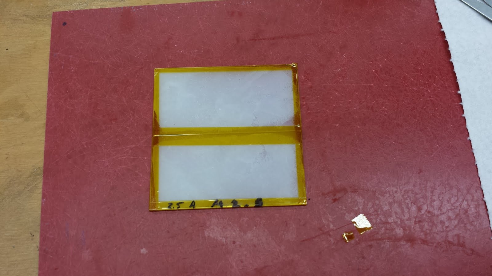
The 1,4 diphenylbenzene (para-Terphenyl or PTP) plated and crystallized in the oven and scintillated. The desired thickness for PTP was 50 micrometers. The actual thickness we got from 2.5g of PTP was 45 micrometers. The plate with 5.0g of PTP had a thickness of 554 micrometers. When the optical fiber was fed into a PMT and placed in a dark box and was hit with the UV LASER, the oscilloscope did detect a successful signal with the blue fiber.
The Anthracene also plated successfully and cleared up in the oven, and scintillated. The desired thickness for Anthracene was 50 micrometers as well. The actual thickness for 2.5g of Anthracene was 31 micrometers. With 5.0g of Anthracene, we achieved a thickness of 41 micrometers. When tested in the darkbox we found that the blue fiber did not sufficiently wave shift and there was no signal at the end of the fiber. The Anthracene emits a higher wavelength than PTP so a higher wavelength wave-shifting fiber was needed. In an attempt to change results, a green fiber replaced the blue fiber which created a successful detection.
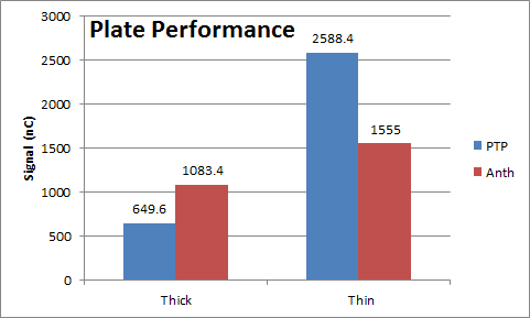
After changing the fibers to the green wave-shifting fiber, signals from both substances were taken. The thin films seemed to do better than the thick ones. The thin PTP was the best and the thick PTP was the worst with the Anthracene performing in the middle. The results of the measurements are expressed in the following table and graph:
Table of Data:
|
Plate Testing |
||
|
Plate |
Pulse (nC) |
Film thickness (um) |
|
PTP 5.0 |
649.60 |
554.14 |
|
PTP 2.5 |
2,588.40 |
45.72 |
|
A 5.0 |
1,083.40 |
41.91 |
|
A 2.5 |
1,555.00 |
30.90 |
|
control |
10.26 |
Graph of Plate Performance:
Further Work:
Finding a way to plate Naphthalene and trans-Stilbene will be helpful. The more options there are, the better. Then, mixing and testing different combinations of the chemicals to get the desired properties and emitted wavelengths could help perfect results. Finding a way to accurately plate Cerium tribromide without wasting it due to its expensive nature would also be interesting. Testing varying thicknesses of the quartz plates and the plated material will be helpful to see if the integration of the optical fiber into the plate can be improved. Stacking plates should also be investigated to see how they perform.